
Engineering guide · sensing cables
How to Select a Fiber Optic Sensing Cable
Choose the cable from the physical quantity, transfer mechanism, environment and installation method—not from the jacket material alone.
Direct answer
The sensing cable is part of the transducer.
A fiber optic sensing cable should be selected by first defining the measurand and how it must be transferred into the fiber. A construction optimized for strain transfer is not automatically suitable for temperature isolation or acoustic coupling.
The final choice must also survive installation and service conditions. Tensile load, bend radius, water, chemicals, crush, temperature range, fixing method, repair strategy and termination all influence the cable structure.
Selection path
Five decisions lead to a defensible cable construction.
Measurement role
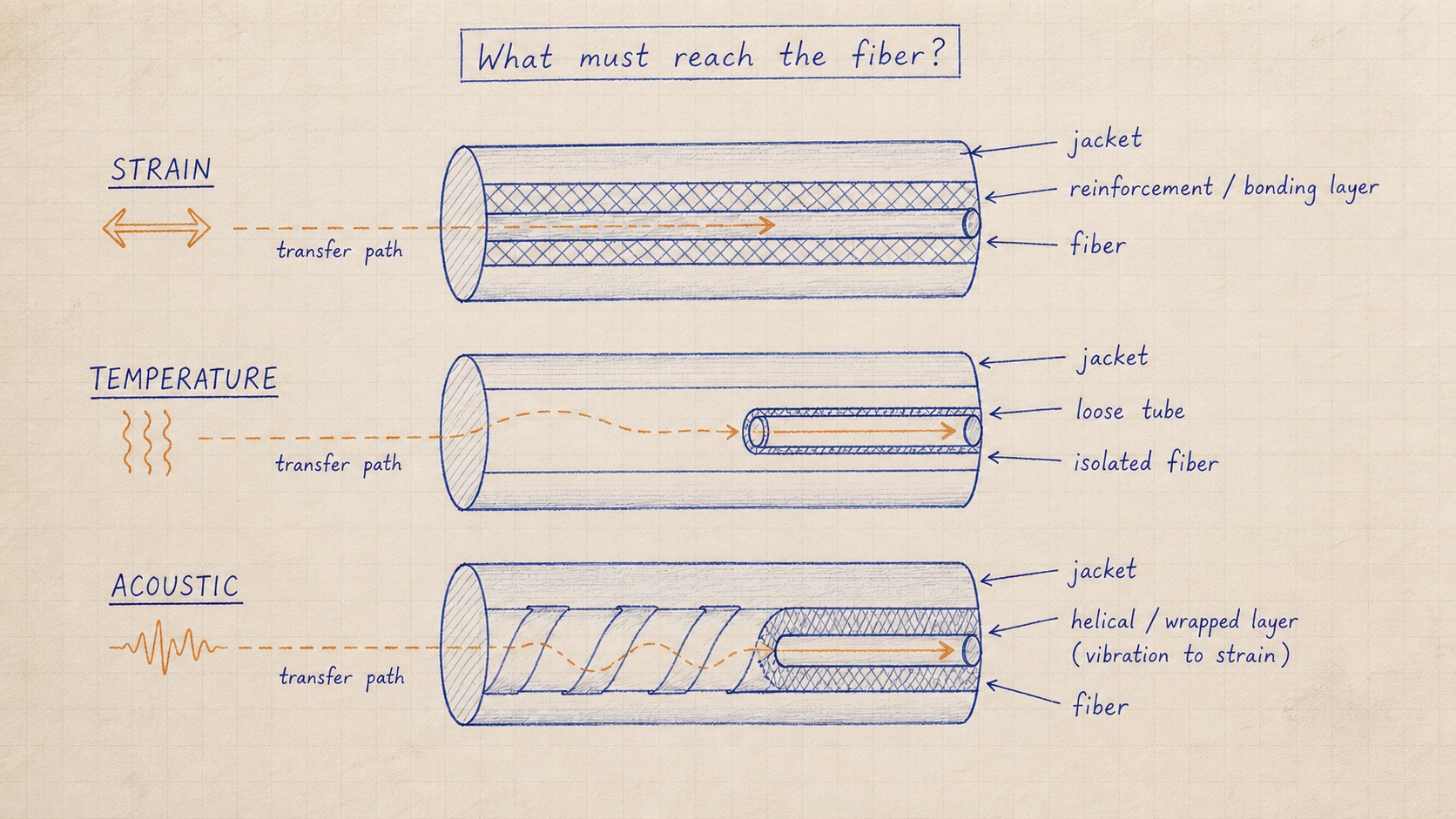
Define what the cable must transfer—or reject.
Strain sensing requires controlled mechanical coupling between the structure, cable layers and fiber. Temperature sensing may need thermal contact while limiting strain transfer. Acoustic sensing needs efficient dynamic coupling in the required frequency band.
If more than one quantity is required, state whether the system will use separate cables, a multi-purpose construction or compensation channels. This choice affects interpretation as much as installation.
- Strain
- Transfer axial deformation predictably and minimize slip.
- Temperature
- Reach thermal equilibrium while controlling mechanical cross-sensitivity.
- Acoustic / vibration
- Couple dynamic pressure or motion into measurable micro-strain.
Transfer mechanism
Trace the load path from the asset to the fiber.
The outer jacket protects the cable, but the buffer, reinforcement, fillers, bonding and sensor position determine the transfer path. A robust cable can still produce poor data if the sensing element is mechanically isolated from the event.
Ask for evidence that represents the required measurement: strain-transfer tests, thermal response, acoustic frequency response, repeatability or installation trials.
Environment and service life
Separate installation survival from long-term measurement stability.
Installation may impose higher pull, crush and bend loads than normal operation. Long-term exposure then adds water ingress, temperature cycling, chemicals, UV, fatigue and creep. Both phases belong in the specification.
Define service temperature, peak temperature, immersion or humidity, chemical exposure, pressure, expected movement and design life. Avoid selecting a jacket only from a generic indoor/outdoor label.
Installation and termination
Design the fixing, routing and repair method before manufacture.
Surface bonding, embedding, trench installation, winding and clamping create different strain-transfer and protection requirements. Lead-fiber length, transition zones, connector type, splice enclosure and access for replacement must be included.
The specified minimum bend radius should apply during installation as well as service. Mark the locations where the sensing portion begins, where reference sections sit and where strain relief is required.
Construction decision
Compare cable families by measurement behavior.
A useful comparison records sensing role, transfer behavior, protection, installation and verification evidence. Diameter and tensile rating alone do not describe measurement performance.
| Need | Likely direction | Evidence to request |
|---|---|---|
| Bonded structural strain | Tight-buffered or bonded reinforcement construction | Transfer efficiency, hysteresis and strain range |
| Distributed temperature | Thermally coupled, mechanically isolated construction | Response time, accuracy and cross-sensitivity |
| Acoustic / vibration | Coupling-focused stranded or purpose-built cable | Frequency response and field coupling test |
| Buried multiparameter route | Layered protected cable or parallel sensing lines | Crush, water, repair and modality separation |
Project worksheet
Information to include in a sensing-cable request
Unknown items can remain open. Marking them clearly keeps assumptions visible during architecture and quotation work.
Frequently asked questions
Questions to resolve before system selection
Can one sensing cable measure strain, temperature and vibration?
It can respond to multiple inputs, but reliable separation requires an intentional cable, reference and interrogation architecture. Separate sensing lines are often clearer when the transfer requirements conflict.
Is a stronger cable always better for strain sensing?
No. Extra reinforcement can improve handling while reducing strain transfer to the fiber. Mechanical survival and measurement coupling must be designed together.
What should be tested before field deployment?
Test the property that matters to the decision: strain transfer and hysteresis, thermal response, acoustic frequency response, environmental resistance, or an installation mock-up.
Define the monitoring boundary
Send the measurement and installation conditions—not only a cable diameter.
Share the worksheet inputs you already know. We can resolve the remaining transfer, protection and interface decisions with you.