Engineering Design and Selection
A practical technology page translating the PPT into cable choice, coating choice, compensation, and lifetime logic.
Engineering Design & Selection
1. Design Principles
Engineering the right UW-FBG sensing system requires translating measurement goals into practical decisions about cable structure, coating material, temperature compensation strategy, and lifetime protection. As illustrated in Figure 1, the selection process follows a logical flow: define the measurement objective, select the appropriate cable structure, choose the coating material that matches environmental conditions, implement compensation where needed, and verify long-term reliability.
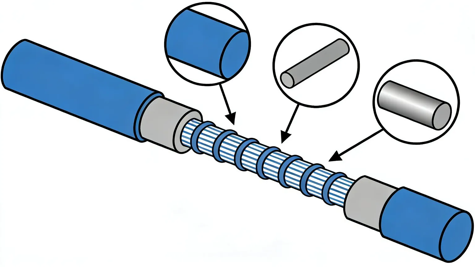
2. Cable Structure Selection
The choice of cable structure determines mechanical coupling between the fiber and the host structure. Three primary configurations address different measurement requirements:
- Loose-tube cable: The fiber sits loosely inside a protective tube, minimizing strain transfer for temperature-only measurements without stress-induced wavelength drift.
- Tight-buffered cable: The coating bonds directly to the fiber for responsive strain transfer, suitable for dynamic structural deformation monitoring.
- FRP-based strain cable: Fiber reinforced polymer encapsulation provides high-fidelity strain transfer with mechanical robustness for embedding in concrete or attaching to steel structures.
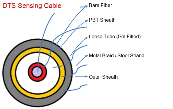
3. Coating Material Compatibility
As shown in Figure 2, coating selection involves evaluating the compatibility between the fiber coating, cable jacket, and the installation environment:
- Acrylate coating: Standard telecom-grade coating for general-purpose sensing up to 85°C; cost-effective for most infrastructure applications.
- Polyimide coating: High-temperature rated (up to 300°C) for industrial environments including power cables, steam pipes, and geothermal wells.
- Metal-coated fiber: Hermetic sealing prevents hydrogen ingress for oil & gas and high-humidity deployments where long-term stability is critical.
- Carbon coating: Provides additional hydrogen resistance and fatigue life for subsea and underground installations requiring 20+ year service life.
4. Temperature Compensation
For precision strain measurements, the apparent wavelength shift caused by temperature must be separated from the mechanical strain signal:
- Co-located reference: A reference FBG in a strain-free tube alongside the sensing fiber provides real-time temperature data for differential compensation.
- Dual-parameter sensing: Two overlapping gratings with different responses to strain and temperature enable simultaneous measurement of both parameters.
- Mathematical compensation: Using known temperature coefficients of the UW-FBG to subtract temperature-induced drift from the combined signal.
5. Lifetime & Reliability
The long-term performance of UW-FBG systems depends on managing environmental degradation factors:
- Hydrogen-related degradation: Hydrogen molecules diffuse into the fiber core and increase optical attenuation, particularly at 1550 nm. Hermetic coatings and hydrogen-resistant fiber formulations mitigate this risk.
- Moisture ingress: Water penetration through cable jackets can cause signal degradation over time. Water-blocking materials and gel-filled cable designs provide protection in wet environments.
- Corrosion protection: For buried or subsea installations, stainless steel or polymer armoring protects against chemical corrosion, while ensuring the mechanical coupling for accurate strain measurement is preserved.
6. Engineering Selection Flow
This decision framework ensures that every UW-FBG deployment is engineered for the specific measurement objective, environmental conditions, and service life requirements of the application.
This is how the final technology page should speak: not only about principles, but about choices.
The PPT also discusses lifetime, hydrogen-related degradation, moisture ingress, corrosion protection, and coating/material compatibility. These are not secondary topics. They determine whether the sensing product survives in real environments.
Related Products
Explore our product portfolio for complete sensing solutions
Ready to Build Your Sensing System?
Talk to our engineers to design a UW-FBG sensing solution tailored to your application.
Talk to an Engineer