
Measurement and range
Identify the primary quantity, expected range and temperature compensation needs.
Monitoring solution
Define the sensing quantity, array geometry, packaging and interrogator requirements for a custom fiber optic sensing system. Start with an engineering brief for research or field deployment.
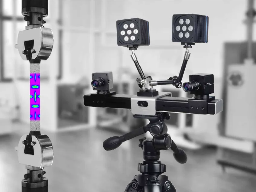
The engineering question
Custom fiber optic sensor design starts with the measurement: strain, temperature or dynamic vibration, the expected range, and the locations that must be observed. Array spacing alone does not define system resolution; the interrogator, sensing cable and installation also determine the usable measurement.
A research setup and a field installation can require different packaging, cable routing, acquisition rates and data interfaces. Define these constraints together before selecting the UW-FBG array and readout architecture. Confirm the achievable specification for the proposed configuration rather than combining limits from different instruments.
Monitoring boundary
Identify the primary quantity, expected range and temperature compensation needs.
Specify sensing length, point count, pitch and uninstrumented lead sections.
Review wavelength, reflectivity, loss budget and connectors with the selected interrogator.
Distinguish grating pitch, gauge length and spatial resolution; specify the required update rate.
Define bonding, embedding or cable mounting, environmental exposure and strain transfer.
Agree output format, synchronization needs, calibration method and acceptance tests.
Sensing chain
Field placement
Share the measurement objective, asset or specimen geometry, operating environment and required coverage.
Prepare an array layout covering sensing locations, lead fibers, routing and connectors.
Review packaging, installation access and compatibility with the intended interrogator.
Agree a configuration-specific specification, calibration approach and acceptance criteria.
Validate the sensing chain under representative conditions before extending deployment.
Document sensor locations, reference readings and data interpretation for the application.
Engineering record
Field evidence
Define the monitoring boundary
These inputs determine the sensing layout more reliably than choosing an instrument first.