
Engineering guide · railway infrastructure
Fiber Optic Monitoring Architecture for Railway Infrastructure
Map railway risks to sensing locations, optical modalities, interrogation and operational responses across track, tunnel, subgrade and adjacent slopes.
Direct answer
There is no single railway fiber-sensing layout.
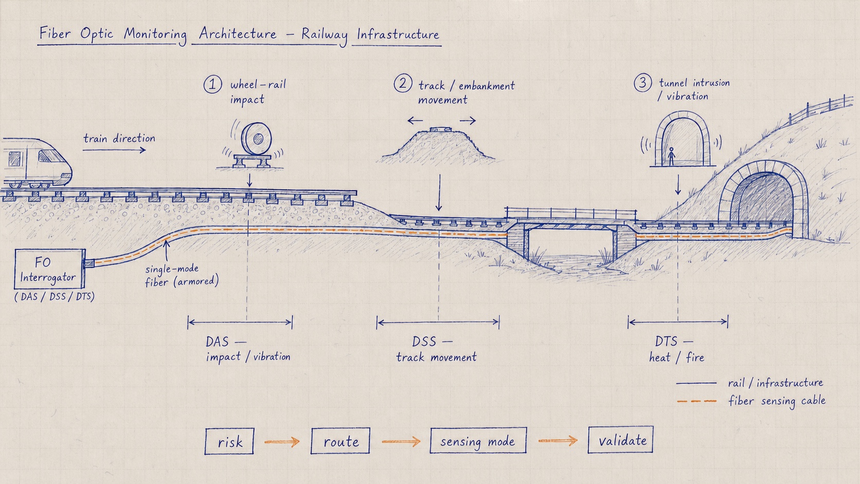
A railway monitoring architecture should separate dynamic events from slow structural change and thermal risk. DAS is suited to localized vibration and acoustic events; DSS to settlement, deformation and load paths; DTS to temperature profiles and fire-related monitoring.
The sensing line should follow the risk: rail or track bed for train-related dynamics, tunnel lining and subgrade for deformation, slopes and approaches for geohazards, and equipment or cable routes for temperature.
Architecture path
Connect the hazard, location, sensing mode and action.
Operational risk
Define the event and the decision it triggers.
Examples include locating a suspected rail break, detecting abnormal wheel or train-induced vibration, tracking subgrade settlement, monitoring tunnel-lining deformation, warning of slope movement, or identifying fire and overheating.
For each risk, define whether the system must detect, locate, classify, quantify, trend or confirm. These verbs produce different data and validation requirements.
Sensing location
Place the sensing line where the physical event is transferred.
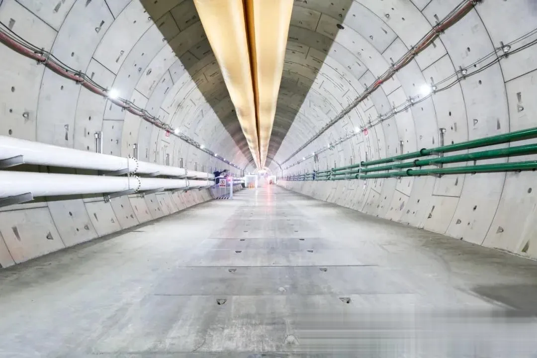
Rail, sleeper or track-bed placement emphasizes train and track response. Embedded or bonded sensing in tunnel linings, retaining structures and subgrade emphasizes distributed deformation. Slope and approach routes require installation that survives ground movement and weather.
Installation access, maintenance windows, cable protection, transition zones and kilometer referencing must be designed with railway operations.
Sensing modality
Assign DAS, DSS and DTS by measured quantity.
DAS provides dynamic waveforms and event location. DSS provides distributed strain or deformation trends. DTS provides temperature profiles. UW-FBG arrays can supply controlled reflection points for high-density strain, temperature or dynamic sensing when matched to the interrogation architecture.
Avoid describing every fiber system as interchangeable “distributed sensing.” Sampling form, gauge length, bandwidth, sensitivity and cable transfer behavior must match the use case.
Interrogation and data
Coordinate channel capacity, clocks and position references.
A multi-modal railway system needs a common route coordinate, asset identifiers and synchronized time. Interrogator range, update rate, frequency band, sensing-point count and communication links must support the operational latency.
Store enough raw or feature-level evidence to validate alarms, but do not move unnecessary data if edge processing can provide a traceable result.
Alarm and validation
Design the response path before enabling automated alerts.
The alert should state what was detected, where it occurred, confidence or severity, supporting channels and the expected operator action. Baselines must include normal trains, maintenance activity, weather and known structural behavior.
| Railway risk | Primary measurement | Architecture output |
|---|---|---|
| Rail or wheel anomaly | Dynamic acoustic / vibration | Located waveform, features and event class |
| Subgrade or tunnel deformation | Distributed strain | Position-referenced trend and threshold |
| Slope or approach movement | Strain plus environmental context | Movement zone, rate and escalation |
| Fire or equipment overheating | Distributed temperature | Hotspot location, temperature and trend |
Project worksheet
Inputs for a railway monitoring architecture
Unknown items can remain open. Marking them clearly keeps assumptions visible during architecture and quotation work.
Frequently asked questions
Questions to resolve before system selection
Can one fiber monitor rail vibration and tunnel deformation?
A coordinated system can cover both, but the cable coupling, sensing mode and interrogation requirements differ. Separate sensing paths or modalities may be required even when they share a route.
Where should railway DAS fiber be installed?
Placement depends on the event. Rail or track-bed coupling emphasizes train and track response; adjacent routes may be better for intrusion or geohazard monitoring. Site trials should verify the transfer path.
How should railway alarms be accepted?
Use representative normal traffic, maintenance and environmental baselines, then controlled or independently confirmed events. Acceptance should include location, detection, false alarms and operator response.
Define the monitoring boundary
Start with the railway risk, sensing location and operator action.
These inputs determine the sensing line, interrogation architecture and validation plan more reliably than choosing an instrument first.