UW-FBG Monitoring for a Reinforced Concrete Slope Facing
Integrating strain and temperature sensing into the reinforcement layout of a slope protection panel, with horizontal and vertical routes planned before concrete placement.
01 / Case overview
Build the monitoring network into the facing.
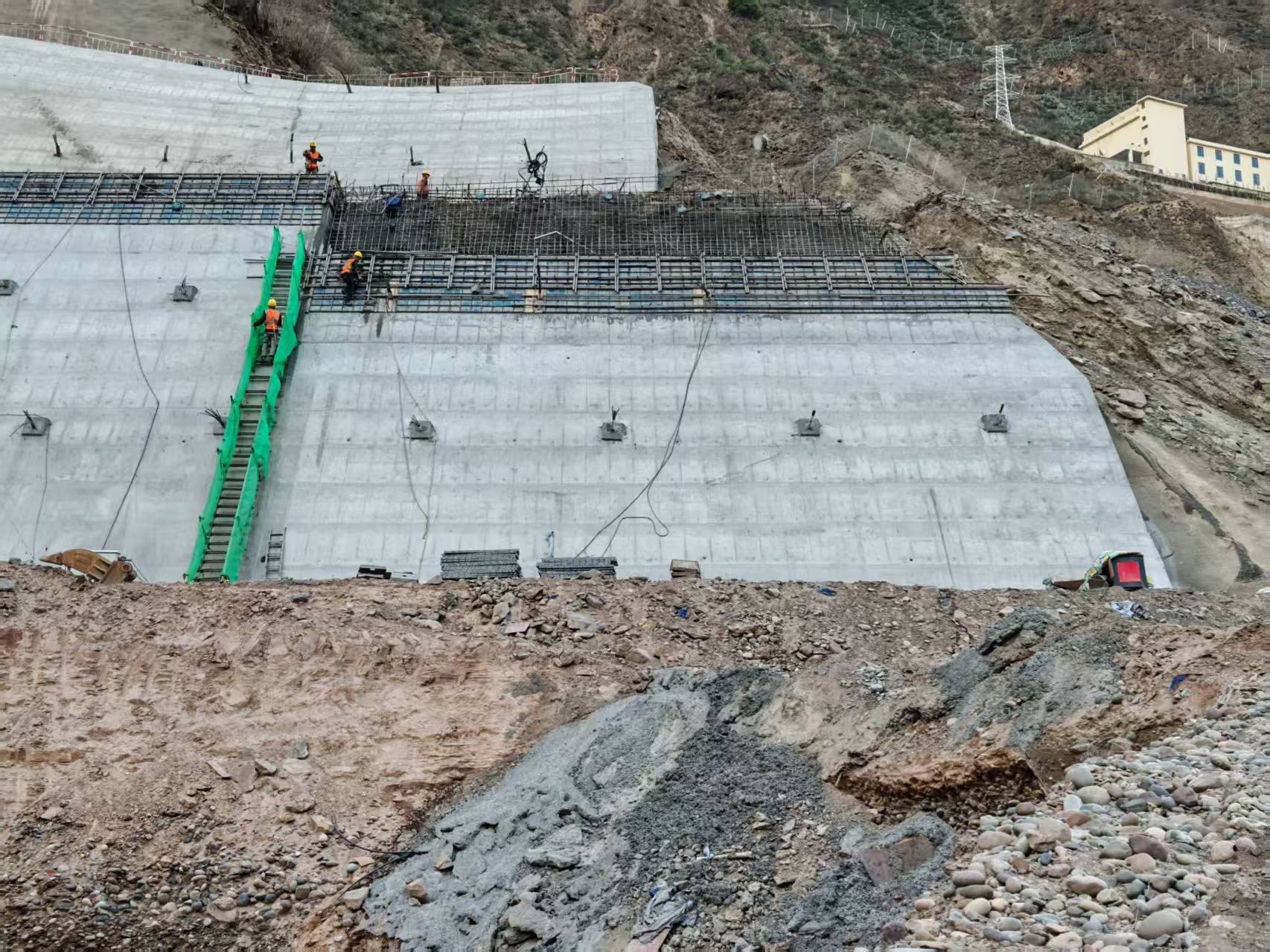
A reinforced concrete facing provides a defined structural surface for monitoring a protected slope. In this project design, ultra-weak fiber Bragg grating (UW-FBG) sensing cables follow the steel reinforcement so that the measurement locations can be related to positions on the panel.
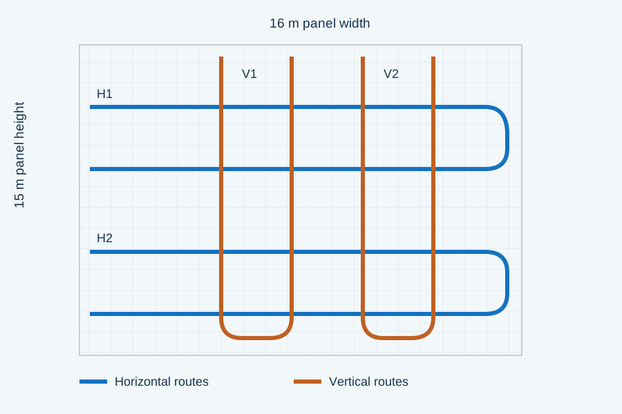
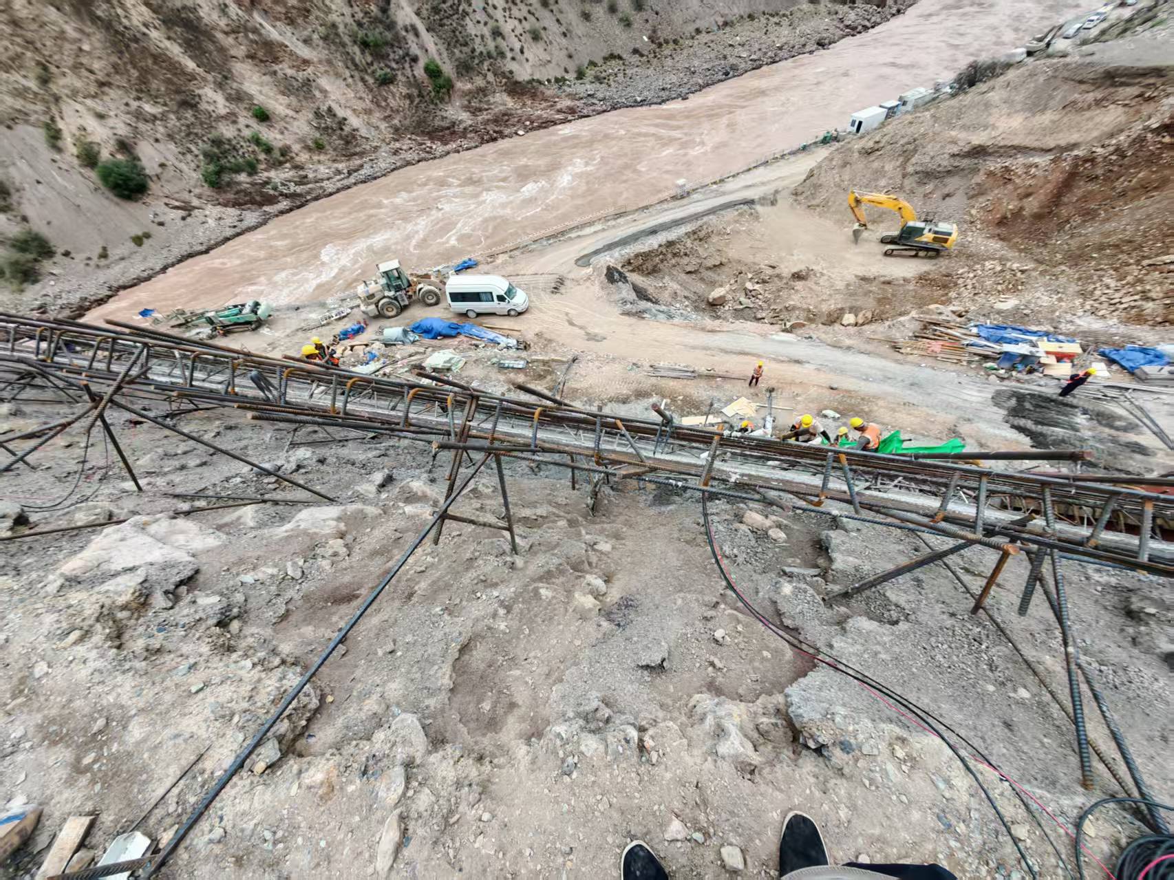
The June 2026 implementation plan specifies separate strain and temperature sensing cables across a panel measuring approximately 15 m high and 16 m wide. Four U-shaped routes provide coverage in two directions, with cable exits brought toward the interrogation equipment.
02 / Monitoring layout
Two directions of measurement across one panel.
Two horizontal U-shaped routes and two vertical U-shaped routes distribute sensing locations across the reinforcement. The layout is intended to help engineers compare strain response at different positions and along different cable directions.
The plan places the lowest horizontal run approximately 3 m above ground and describes approximately 3 m spacing between horizontal levels. Vertical cable legs are spaced approximately 3.2 m apart.
Temperature cables provide a parallel temperature record for interpreting strain response. A compensation method must be established using the selected cable calibration and installed point mapping.
03 / Installation method
Coordinate cable installation with each concrete pour.
- Identify and mark sensing positions. Connect the cable to the interrogator, identify the starting position and use cable metre marks to map grating locations to the structure.
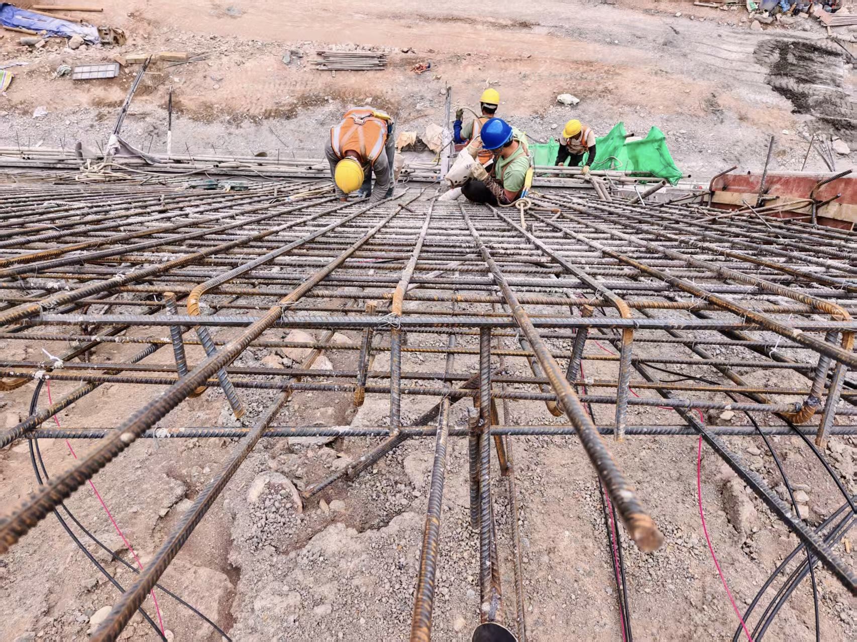
- Secure the sensing runs. The plan calls for steel ties to fix the sensing cable to the corresponding reinforcement, with installation intended to transfer structural strain to the cable.
- Protect turns and transitions. Use the planned protective tubing and curved reinforcement supports at bends. Confirm bend limits against the approved cable specification.
- Follow the construction sequence. Coordinate routing with reinforcement installation and concrete placement so that cables remain at their intended positions and are protected from interruption or breakage.
- Connect before placement. Bring the cable ends to the mobile monitoring station before concreting, as specified in the implementation plan.
04 / Design configuration
Cable selection follows the installation environment.
The plan identifies RS-CABLE-S4-5.0 for the sensing cable specification and allocates 250 m each for strain and temperature cabling. These are planning quantities, including routing and allowance requirements, rather than verified installed lengths.
- Strain cable grating pitch
- 1 m, as specified in the plan
- Specified cable diameter
- 5.0 ± 0.5 mm
- Outer sheath
- Black polyethylene (PE)
- Specified operating temperature
- −20°C to +85°C, cable specification
- Planned strain cable
- 250 m
- Planned temperature cable
- 250 m
- Planned protection tubing
- 40 m
05 / Engineering value
Connect each reading to its structural location.
The design provides a practical basis for comparing strain along horizontal and vertical routes while retaining a separate temperature record. Embedding the network during construction creates an opportunity to follow the facing response from concrete placement into subsequent observation.
Its engineering value depends on reliable strain transfer, cable survival during construction, correct location mapping and an agreed reference measurement. These are central to interpreting a change in the optical signal as a change in the structure.
Technical questions
What does this monitoring design measure?
Does this case measure the movement of the entire slope?
The network is designed to monitor strain and temperature associated with the concrete facing. Whole-slope displacement, deep sliding surfaces and stability assessment require additional project-specific measurements and engineering interpretation.
Does 1 m grating spacing mean 1 m measurement accuracy?
No. Grating spacing describes the distance between specified sensing locations along the cable. Measurement accuracy, gauge length and effective spatial resolution are separate characteristics of the cable and interrogation system.
Is vibration monitoring included in this case?
The implementation plan mentions vibration as a potential monitoring objective, but does not define a project-specific dynamic interrogation configuration or present vibration results. This case therefore focuses on the documented strain and temperature design.
Discuss your project
Planning monitoring for a concrete slope facing?
Share the panel dimensions, reinforcement layout, concrete placement sequence and required measurements. Our engineering team can help define the sensing routes, cable package and interrogation configuration.