DAS Avalanche Early Warning Application Case

This application case is adapted from the provided project proposal “BA25101509 Avalanche DAS High-Resolution Dynamic Hazard Early Warning Solution.” It is written for the Applications section of an independent website and focuses on the engineering value of DAS-based long-distance, continuous, real-time avalanche vibration monitoring.
1. Case Overview
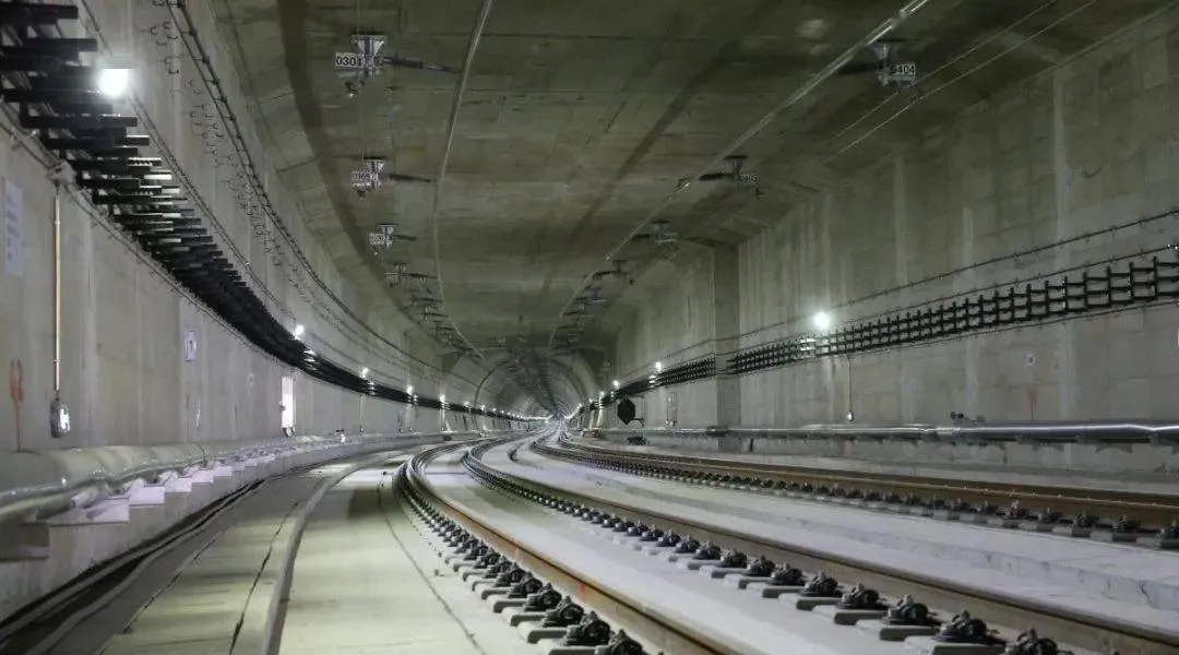
In high-altitude mountain regions such as the Qinghai-Tibet Plateau, the Tianshan Mountains and the Altun Mountains, avalanches pose serious risks to transport corridors, energy routes, transmission lines, pipelines and tourism areas. Manual inspection is inefficient and dangerous; video monitoring can fail in snowstorms, fog and night-time conditions; and seismic arrays are point-based systems that may miss spatially distributed avalanche dynamics.
This case presents a high-resolution DAS (Distributed Acoustic Sensing) avalanche early-warning solution. By deploying a dedicated sensing cable along a high-risk slope, the system converts the cable into a continuous vibration sensing array. It is designed to monitor the initiation, movement and disturbance characteristics of avalanche-related dynamic events and to support early warning and emergency response.
The DAS system transforms a long sensing cable into a continuous vibration sensing network, providing all-weather monitoring capability for high-risk alpine regions where conventional visual or point-based monitoring methods are limited.
2. Project Background and Monitoring Objectives
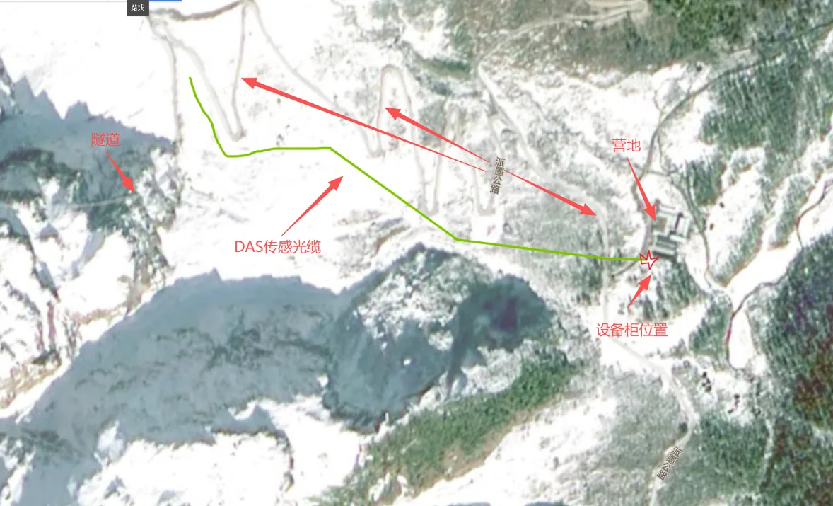
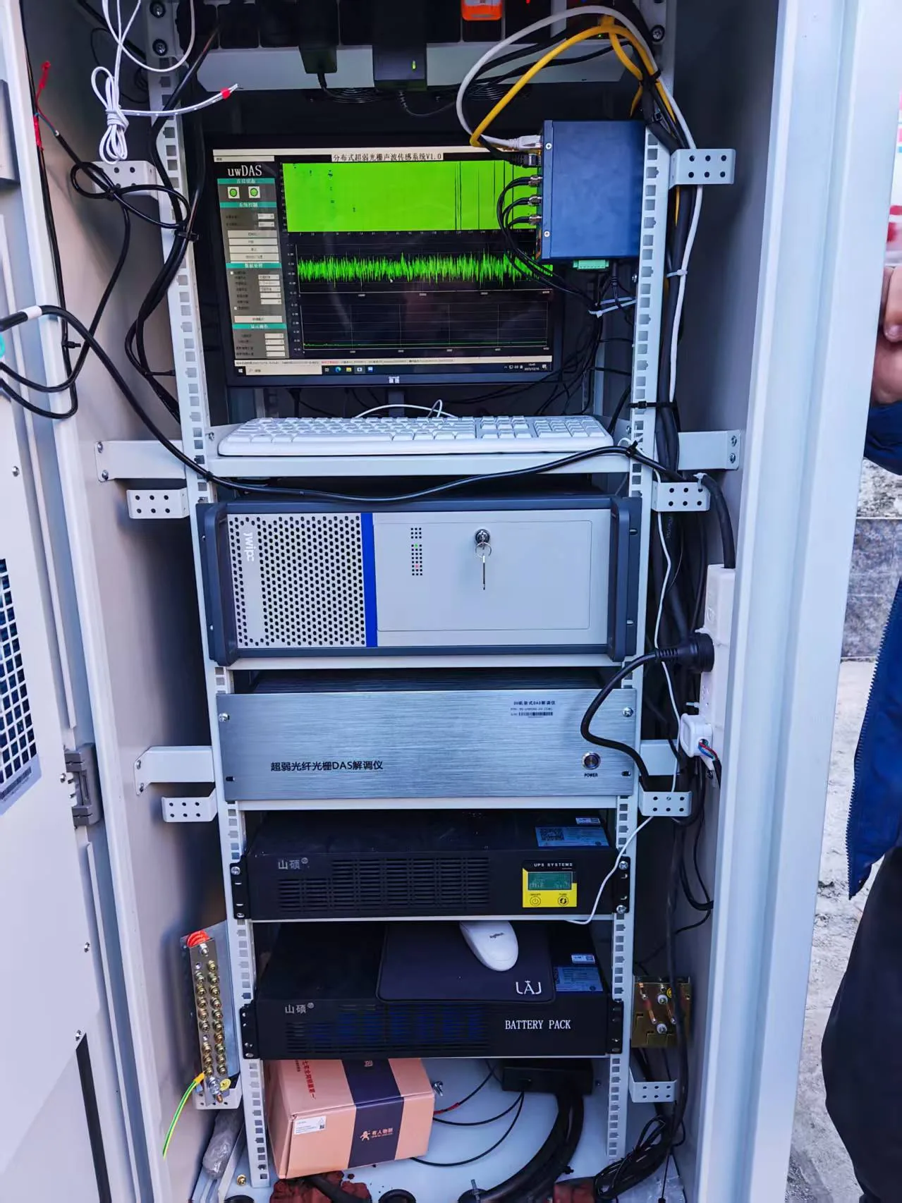
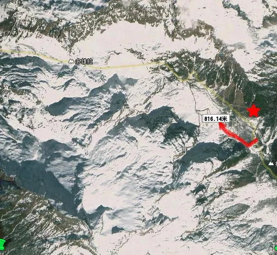
The project plans to deploy approximately 300 m of dedicated sensing cable upward along a high-risk avalanche slope, with an installation interval of approximately 5 m to form a dense vibration sensing line. A reinforced-concrete bunker at the foot of the slope serves as the core equipment room, hosting the DAS interrogator, data acquisition server, network equipment, power system, UPS and battery bank for 24/7 operation.
| Project Element | Description |
|---|---|
| Monitoring object | Avalanche-related low-frequency vibration signals and disturbance events along the slope |
| Typical deployment | Approx. 300 m sensing cable from the bunker to the monitored slope area, with approx. 5 m spacing |
| System objective | Continuous acquisition, event identification, alarm rule judgment, location / intensity / estimated scale reporting and emergency linkage |
| Operating environment | High altitude, low temperature, strong snow and wind, low visibility and remote operation |
| Operational support | Utility power + UPS + battery bank, insulated / air-conditioned outdoor cabinet, network communication and remote control |
3. System Requirements and Key Parameters
| Requirement | Technical Target |
|---|---|
| Overall requirement | Continuous acquisition of avalanche low-frequency vibration signals |
| Sensing cable requirement | Cable strength suitable for possible avalanche impact and harsh outdoor environments |
| Instrument frequency range | Low-frequency monitoring: 0–50 Hz |
| Monitoring threshold | Vibration intensity ≥ 0.1 rad |
| Spatial resolution | 5 m |
| Operating temperature range | -20 °C to 60 °C |
| Acquisition length | ≥ 3 km |
| Supporting requirements | On-site storage > 40 TB; outdoor cabinet with thermal control / air conditioning; 220 V remote controller |
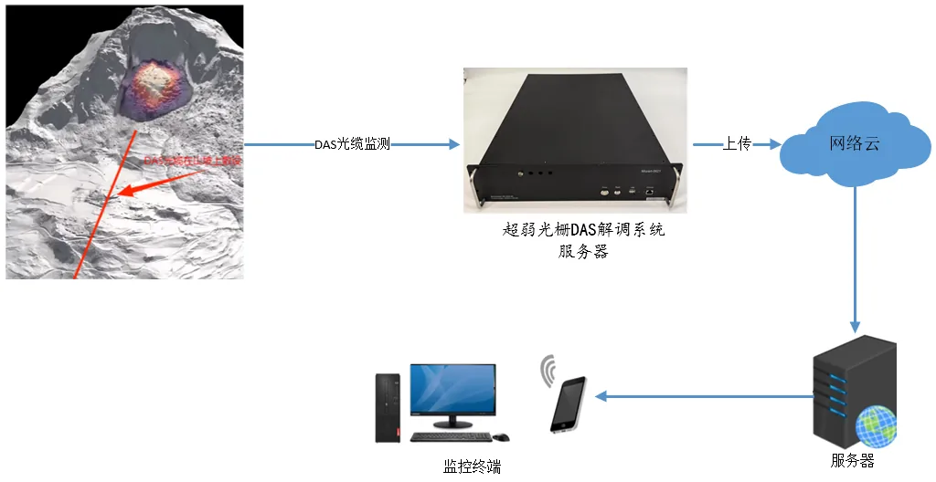
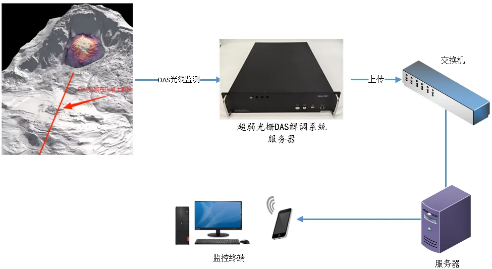
4. System Architecture and Deployment Method
During construction-stage operation, data collected by the DAS interrogator in the bunker can be transmitted to a cloud monitoring platform through optical fiber or 4G wireless network. For long-term operation, wired network or a private network is recommended to improve reliability and reduce recurring wireless communication cost. The platform receives alarm information and uses location, vibration features and time-frequency analysis to support event judgment.
The sensing cable is routed from the bunker to the monitored slope along a pre-surveyed path. To ensure strong coupling with the ground and protect the cable from mechanical damage, direct burial is recommended where possible. A shallow trench of approximately 30–50 cm is excavated, the cable is laid and backfilled with fine sand or local soil, and the surface is compacted. In rocky areas where trenching is difficult, the cable can be fixed to the surface with U-shaped nails or dedicated clamps.
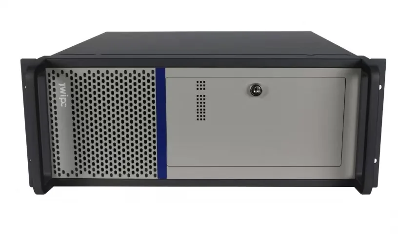
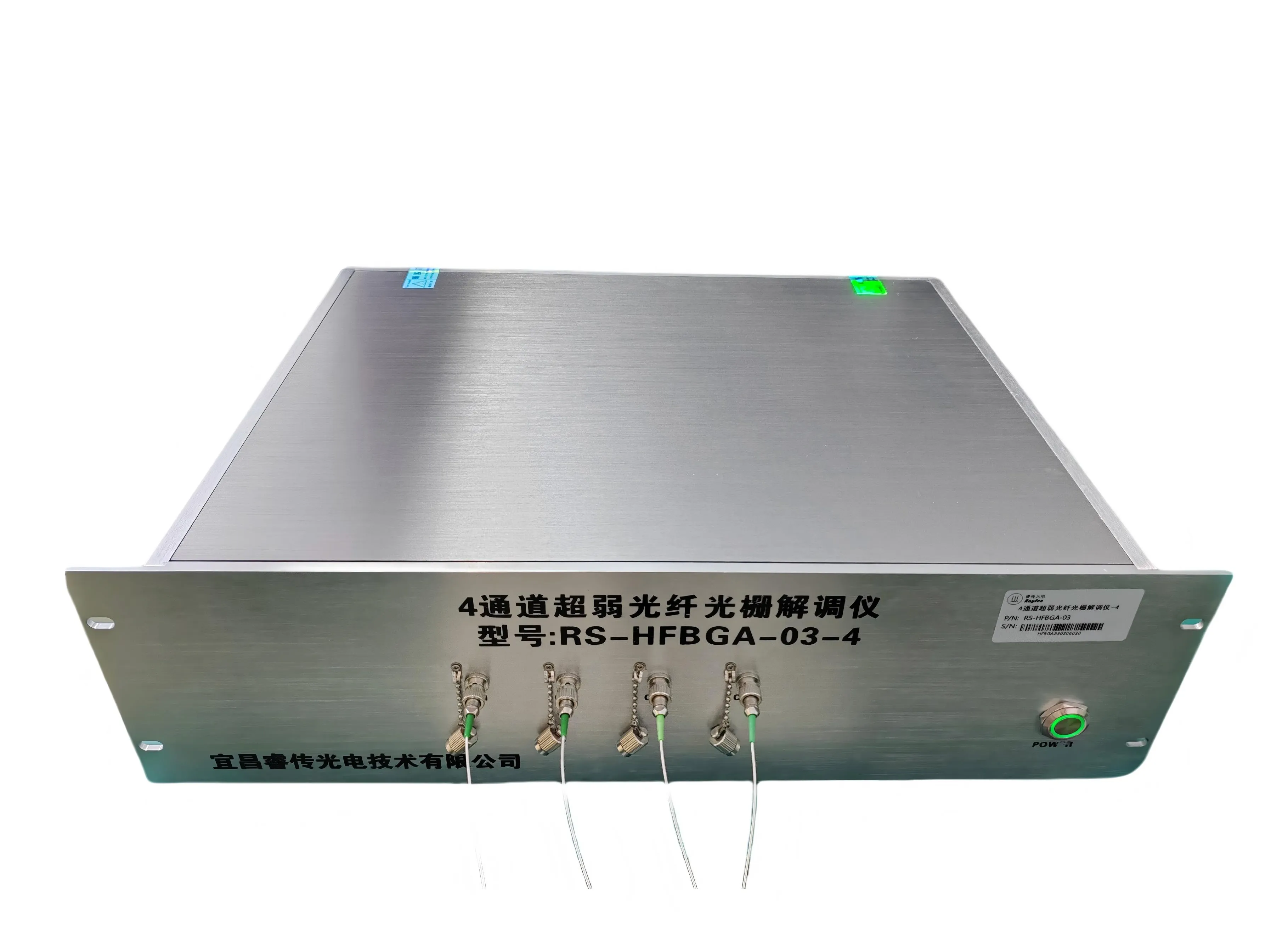
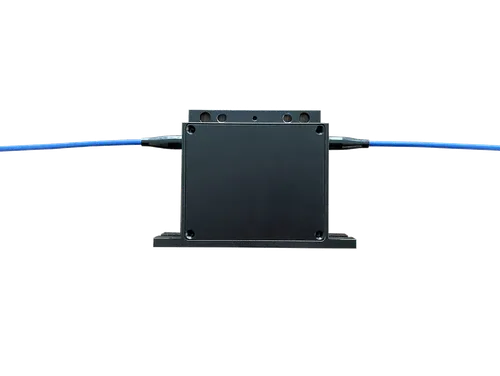
5. Core Equipment and Sensing Cable
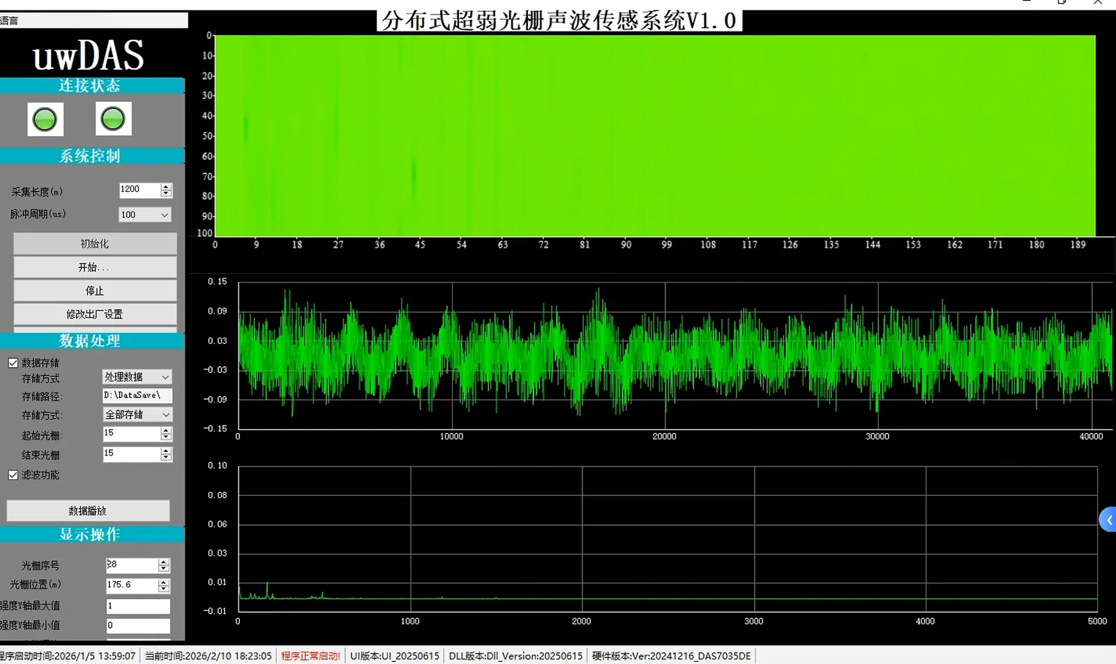
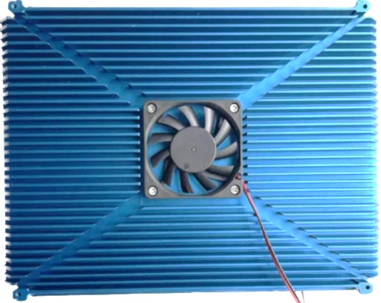
The solution uses an ultra-weak grating DAS interrogator to acquire vibration signals from the sensing cable. Near-infrared laser pulses propagate along the sensing fiber and are reflected at grating locations. After 3×3 phase compensation and interference processing, the returned signals contain vibration information along the cable. A high-performance ARM + FPGA SoC performs real-time phase demodulation to address large-scale data processing requirements.
| DAS Interrogator Parameter | Specification |
|---|---|
| Sensitivity | ≤ 0.5 nε |
| Wavelength and channel | 1550.12 nm, single channel |
| Grating reflectivity | 0.01% |
| Demodulation spatial resolution | ≥ 5 m |
| Measurement distance | 2.5 km |
| Output interface | Gigabit Ethernet |
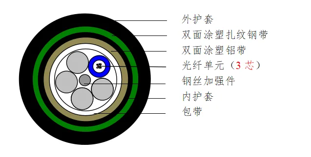
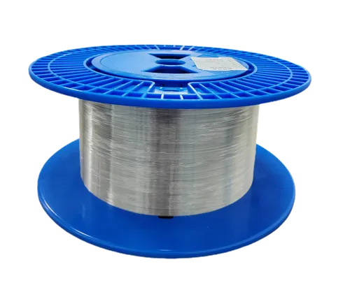
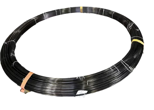
The communication trunk cable is a steel-sheathed stranded direct-burial DAS cable. It is designed for waterproofing, tensile strength, crush resistance, rodent protection, cut resistance and bending resistance, making it suitable for direct burial, aerial laying or duct installation. The typical cable diameter is approximately 12.5 ± 0.5 mm, and the cable integrates DAS vibration fiber, strain fiber and G.652D bare fiber.
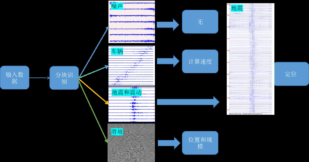
6. Data Acquisition, Recognition and Alarm Workflow
The monitoring software continuously reads the latest vibration data from the DAS system. The workflow first applies time-domain screening based on amplitude range, vibration intensity and signal-to-noise level within a time window. Filtered data are then analysed in the frequency domain. Alarm rules can be configured in the host software, and confirmed warnings can be pushed through an API to a command center or emergency management platform.
7. Field Operation Notes and Engineering Optimization
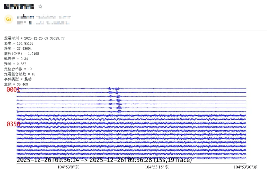
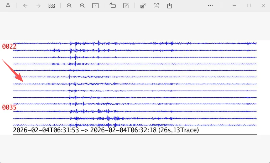
The system installation was completed efficiently, with well-organized field equipment and materials. The system has reportedly operated stably for approximately three months. No avalanche event has occurred during the observed period, and no false avalanche alarm has been reported. Because the sensing cable passes through a culvert, vehicle passage during non-closure periods can create significant interference in certain sensing segments, which should be addressed through event classification and interference rejection.
| Optimization Area | Recommendation |
|---|---|
| Low-frequency capability | The project requirement includes 0.1–2.5 Hz vibration acquisition; this band requires further verification and optimization. |
| Data format compatibility | The customer requested TDMS format; data export or format conversion should be added where needed. |
| Interference recognition | Vehicle passage generated interference in sensing segments 8–36; traffic / construction disturbance samples should be included in the recognition model. |
| Cabinet integration | Cabinet door type, wiring space, waterproofing and thermal control should be confirmed before procurement and delivery. |
| Alarm strategy | Any avalanche event detected by the system should be treated as a high-priority event for review and emergency response. |
8. Conclusion
This application case demonstrates a system-level route for DAS-based avalanche dynamic hazard monitoring. By combining slope-deployed sensing cable, bunker-based equipment housing, a DAS interrogator, redundant power, data platform and alarm linkage, the solution creates a continuous vibration sensing system for high-altitude, high-risk and low-visibility mountain regions. The current deployment validates field installation and stable operation, while future work should focus on ultra-low-frequency response, data-format compatibility, environmental interference recognition and avalanche-event sample accumulation.
Yichang Raysensing Optoelectronics Technology Co., Ltd.
Website: www.ray-sensor.com | Email: tim@ray-sensor.com
Other Cases
Explore more case studies in Railway & Transportation

Related Products
Explore our product portfolio for complete sensing solutions
Have Questions? Talk to an Engineer
Our engineers are ready to discuss your DAS avalanche monitoring requirements and help design the right solution for your application.
Talk to an Engineer