
Engineering guide · UW-FBG arrays
How to Specify a Custom UW-FBG Sensor Array
Translate the measurement boundary, sensing-point layout, environment and data requirement into a specification that the array, cable and interrogator can satisfy together.
Direct answer
Start with the measurement boundary, not the catalogue.
A useful custom UW-FBG specification connects five decisions: what must be measured, where the sensing points must sit, how the optical array will be read, how the fiber will transfer the physical input, and what data the monitoring system must deliver.
Array pitch or reflectivity should not be selected in isolation. They are coupled to array length, point count, cable construction, optical loss, interrogation method, sampling rate and the scale of the event being observed.
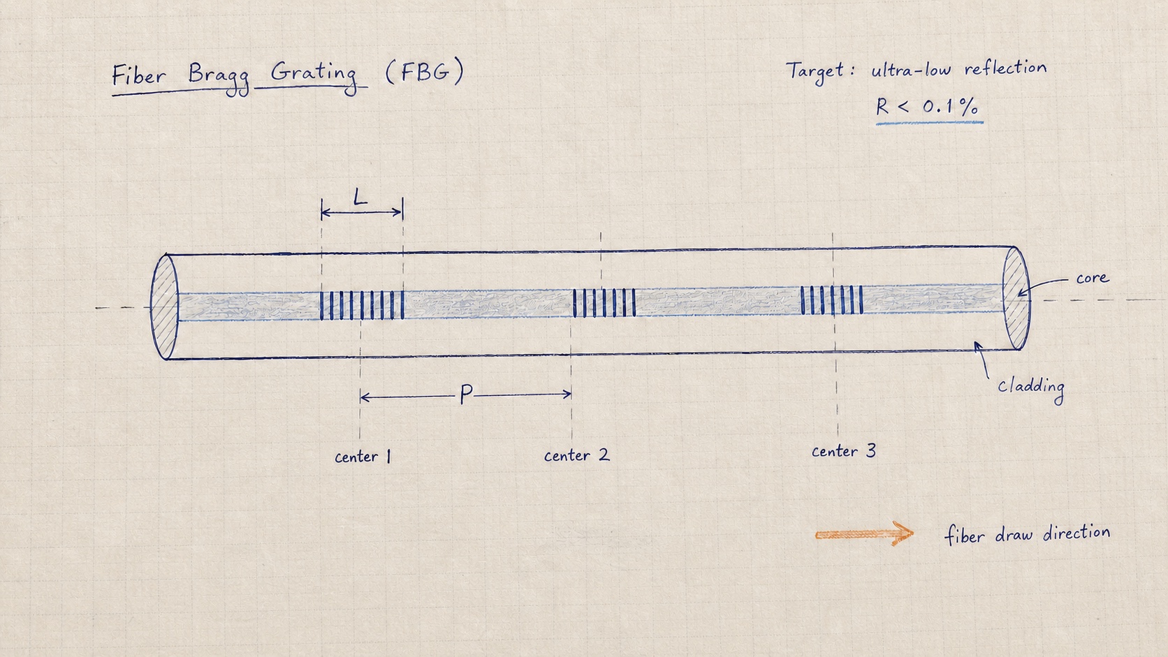
Working array sketch
Turn the sensing layout into buildable grating geometry.
Where and what to measure
Define the physical event before the sensor layout.
State the primary measurand—strain, temperature, humidity, acoustic response or vibration—and whether the result is static, quasi-static or dynamic. Then define the asset length, critical zones, event size and the resolution required to make an engineering decision.
- Asset boundary
- Total monitored length and locations that cannot be left unobserved.
- Decision threshold
- The change that must be detected, not merely the instrument resolution.
- Response type
- Long-term drift, transient load, acoustic event, temperature profile or combined measurement.
Array geometry
Set point spacing from the event scale and installation geometry.
The point spacing must be fine enough to resolve the expected strain, thermal or acoustic pattern, but it should not be reduced without purpose. A denser array increases sensing-point count and data load, and it must remain compatible with the interrogation architecture and optical budget.
Add lead fiber, transition zones, reference elements and installation reserve separately.
Optical design
Treat reflectivity and wavelength as system parameters.
Ultra-low reflectivity supports dense arrays by limiting shadowing and multiple-reflection crosstalk. The required value is selected with the full link budget: array length, number of gratings, fiber attenuation, splices, connectors, interrogation architecture and required signal-to-noise ratio.
RaySensing array families support project-defined wavelength, spacing, reflectivity, coating and package form. The final optical configuration should be confirmed against the intended interrogator rather than copied from an unrelated project.
Read the UW-FBG array physics →Mechanical transfer
Specify how the physical input reaches the fiber.
The same optical array can behave very differently when it is bare, tight-buffered, bonded to a reinforcement element or integrated into a purpose-built sensing cable. Packaging determines strain transfer, thermal response, acoustic coupling, protection and installation repeatability.
| Installation need | Packaging direction | Design check |
|---|---|---|
| Laboratory or embedded array | Bare/coated or compact buffered fiber | Handling, bonding and bend control |
| Surface strain transfer | Tight buffer, strip or bonded reinforcement | Transfer efficiency and adhesive system |
| Harsh field deployment | Engineered sensing cable | Crush, tensile, water and chemical exposure |
| Acoustic or vibration response | Coupling-focused cable or probe | Frequency band and installation contact |
Interrogation and output
Match the array to the required update rate and data product.
A static deformation profile, high-speed acoustic event and temperature trend require different interrogation and processing paths. Record the required update rate, usable frequency range, channel count, synchronization, raw-data access and output interface before the array is frozen.
- Interrogation method and supported wavelength range
- Static update rate or dynamic sampling/frequency requirement
- Maximum channel and sensing-point count
- Required outputs: wavelength, strain, temperature, waveform, event location or API stream
- Synchronization, trigger and integration requirements
Project worksheet
Information to include in a custom-array request
Unknown items can remain open. Marking them clearly allows the optical and mechanical design to be resolved without hiding assumptions.
Frequently asked questions
Questions that should be resolved before fabrication
Which information should be defined before requesting a custom UW-FBG array?
Define the measured quantity, sensing length, required point spacing, operating environment, installation method, dynamic or static response, interrogator interface, lead-fiber length, connector, and expected data output. These inputs are more useful than selecting a model number first.
Does closer grating spacing always produce a better system?
No. Closer spacing increases the number of sensing points and data volume, and it must remain compatible with the interrogation method, spatial resolution, optical power budget, installation geometry, and the physical scale of the event being measured.
How is grating reflectivity selected for a long UW-FBG array?
Reflectivity is selected as part of the complete optical budget. Array length, point count, fiber attenuation, connector and splice losses, interrogation architecture, detector sensitivity, and required signal-to-noise ratio must be considered together.
Can one UW-FBG array measure strain and temperature at the same time?
A grating responds to both strain and temperature, so simultaneous recovery requires an appropriate compensation or decoupling architecture. This may use paired sensing references, isolated temperature elements, packaging design, or a multi-parameter calibration model.
Define the monitoring boundary
Send the application constraints—not just a part number.
Share the worksheet inputs you already know. Our engineers can identify the remaining optical, cable and interrogation decisions with you.