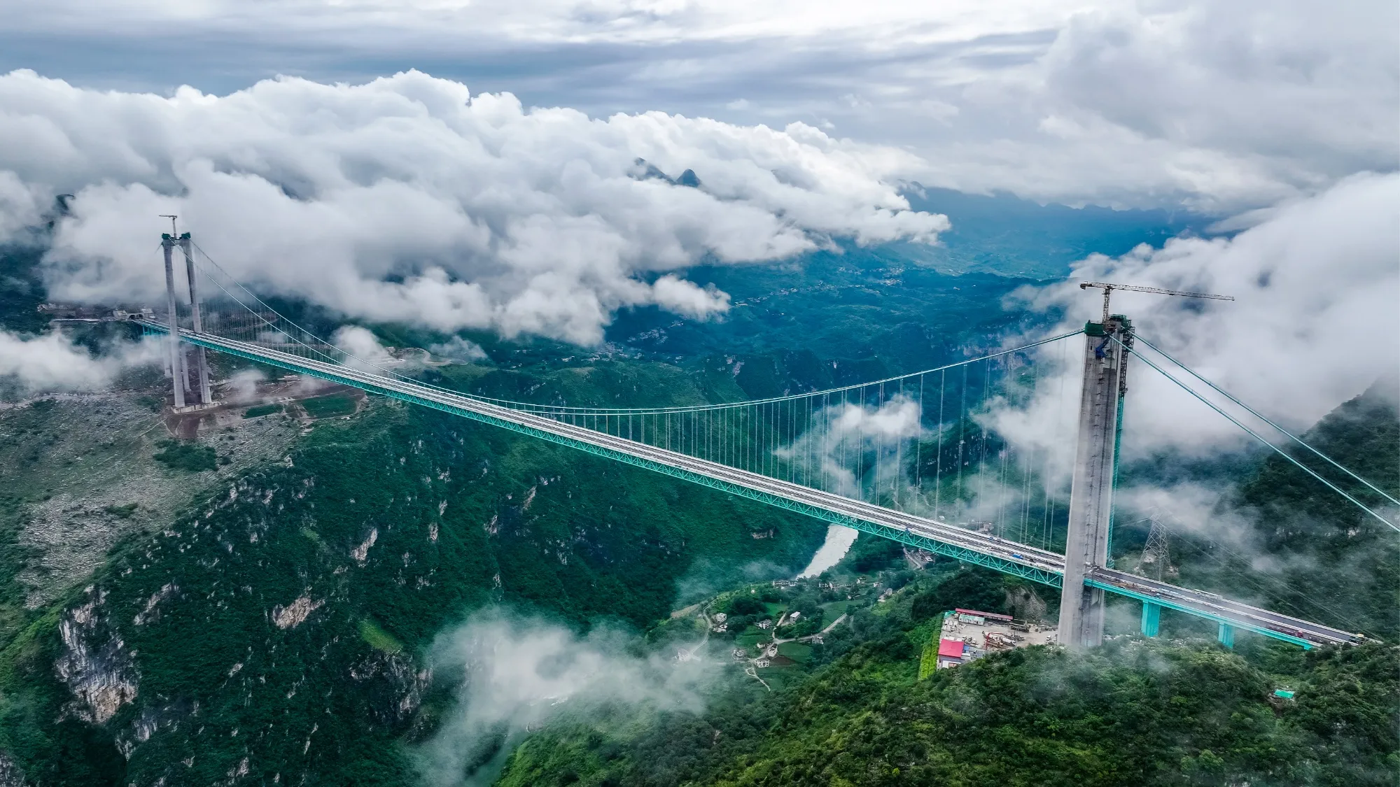
Global load response
Distributed strain profiles along girders and decks show how load is transferred across the span.
Bridge & large structure monitoring
A bridge is a connected load path. Distributed fiber sensing follows strain, temperature, deformation and vibration across that path instead of reducing the structure to a few isolated points.

The monitoring question
Traffic, wind and temperature do not act at one point. Their effects travel through decks, girders, bearings, cables and connections. Sparse sensors can verify selected locations, but they can miss the transition between them.
The system therefore begins by defining the load path, the required spatial coverage and the time scale of the behavior before selecting the sensor cable or interrogator.
Monitoring plan
Distributed strain profiles along girders and decks show how load is transferred across the span.
Spatial temperature data separates thermal expansion from load-induced strain and supports compensation.
Denser arrays or point FBG sensors focus on bearings, joints, cable anchorages and known stress concentrations.
Dynamic strain or acoustic sensing captures vibration as vehicles, wind and transient events excite the structure.

The sensing chain
The array, cable structure, bonding method, interrogator and interpretation model must transfer the same physical event without losing its spatial meaning.
Field reference
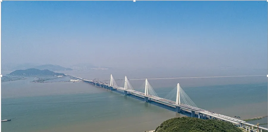
UW-FBG arrays were arranged along the bottom plate and webs of the 340 m main-span box girder. The layout was used to recover strain and deformation under static and dynamic loading rather than relying on a single instrumented section.
Related field evidence
Define the monitoring boundary
These inputs determine the sensing layout more reliably than choosing an instrument first.