Demodulation and Interrogation Technologies
From classic FBG interrogation to high-speed UW-FBG demodulation, this page explains how optical signals become usable sensing outputs.
Demodulation and Interrogation Technologies
1. What is Demodulation?
In fiber optic sensing, demodulation (also called interrogation) is the process of converting the optical response from a sensing fiber into measurable physical quantities — strain, temperature, or vibration. For UW-FBG systems, the interrogator emits laser pulses into the fiber and analyzes the reflected signals from each grating to determine wavelength shifts that correspond to environmental changes.
2. Scanning Light-Source Demodulation
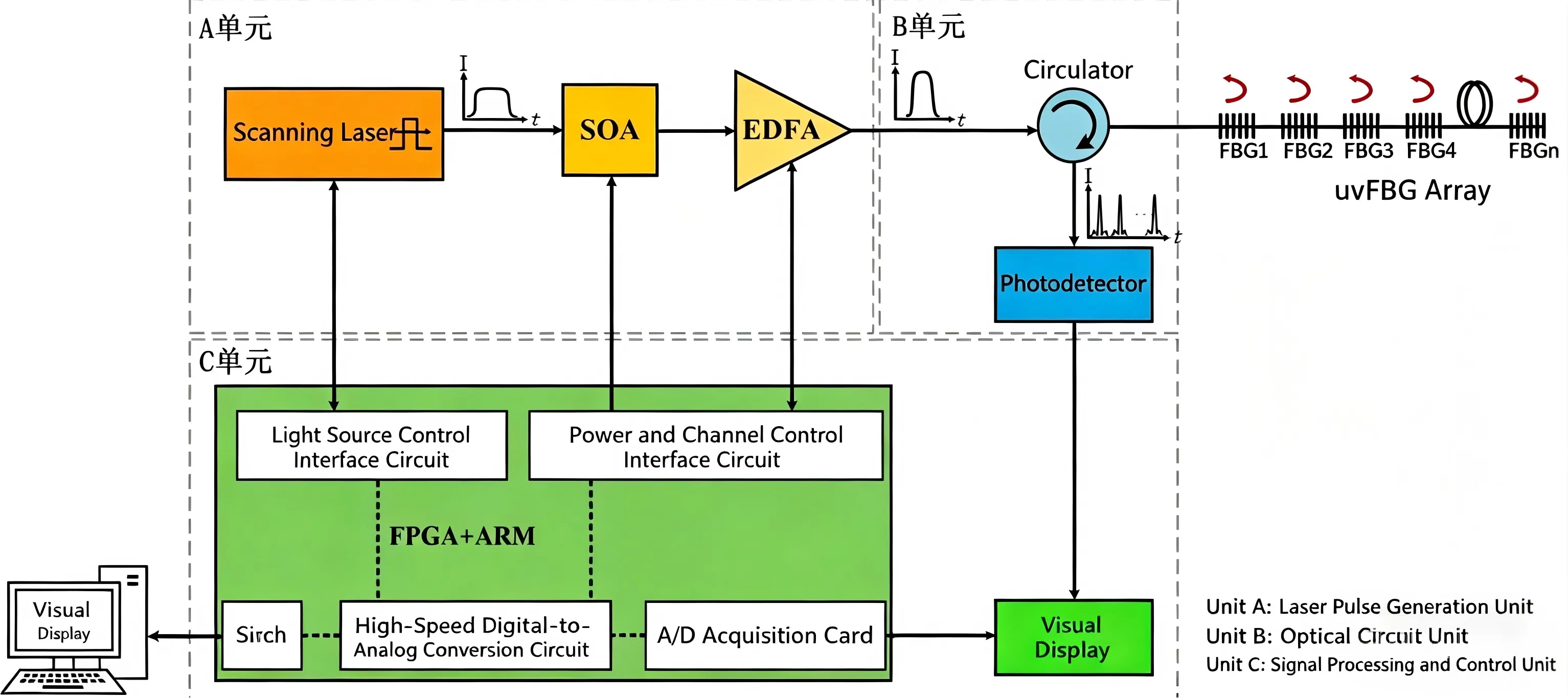
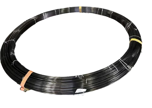
As shown in Figure 1, scanning light-source demodulation works by sweeping a tunable laser across a wavelength range. When the laser wavelength matches a grating's Bragg wavelength, a reflected pulse is detected. The system records the time-of-flight for spatial positioning and the wavelength shift for the measured parameter (strain/temperature). This method is widely used in UW-FBG systems because it supports a large number of gratings on a single fiber while maintaining high wavelength resolution.
3. Time-Domain Positioning
Each UW-FBG grating reflects a signal at a known time delay corresponding to its position along the fiber. The interrogator calculates the distance to each grating using:
where c is the speed of light, Δt is the round-trip time, and neff is the effective refractive index of the fiber core. This enables precise spatial localization of each sensing point along kilometers of fiber.
4. System Architecture
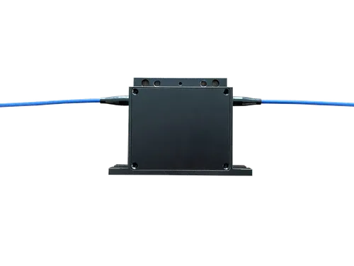
As illustrated in Figure 2, a complete UW-FBG demodulation system comprises four key subsystems:
- Laser Source: A tunable or pulsed laser that generates the optical interrogation signal with specific wavelength and power characteristics.
- Optical Routing: Circulators and couplers that direct laser pulses into the sensing fiber and route reflected signals to the photodetector.
- Detection & Acquisition: High-speed photodetectors and digitizers that convert the weak optical reflections into electrical signals with nanosecond timing resolution.
- Control & Processing: A system-on-chip (SoC) combining ARM and FPGA for real-time signal processing, wavelength demodulation, and data output.
5. Performance Factors
- Acquisition speed: Determines the maximum measurable vibration frequency (e.g., 10 kHz sampling enables 5 kHz acoustic sensing per the Nyquist criterion).
- System bandwidth: Defines how many gratings can be interrogated per second — higher bandwidth supports faster scanning across more sensing points.
- Wavelength resolution: Sub-picometer wavelength accuracy is required for micro-strain level detection sensitivity.
- Signal-to-noise ratio: Weak UW-FBG reflections (0.01%–1%) demand high-sensitivity detectors and advanced signal processing algorithms.
/s15_1.webp)
That is the cleanest way to explain the system without burying the user in circuit details.
The PPT also shows the kinds of interfaces users finally see: time-domain positioning, spectrum analysis, single-grating wavelength, and wavelength-array stability views.
Related Products
Explore our product portfolio for complete sensing solutions
Ready to Build Your Sensing System?
Talk to our engineers to design a UW-FBG sensing solution tailored to your application.
Talk to an Engineer